

Custom Ultrasonic Spray Pyrolysis System for Precise Thin Film Engineering
2026-10-21
Thin film deposition often feels like a compromise—precision sacrificed for speed, or customizability traded for cost. But what if you didn't have to choose? Enter the custom ultrasonic spray pyrolysis system from Siansonic, engineered to give researchers and manufacturers a level of control over film thickness, composition, and morphology that traditional methods simply can't match. In this post, we'll break down how this system redefines precise thin film engineering, from nanoparticle synthesis to scalable coating processes—and why it might be the missing piece in your materials lab or production line.
Why Off-the-Shelf Ultrasonic Spray Pyrolysis Fails on Thin Film Uniformity
Standard ultrasonic spray pyrolysis rigs assume a stable aerosol plume and uniform droplet residence time, but commercially available nozzles rarely deliver either. The piezoelectric transducer vibrates at a fixed frequency, producing droplets with a narrow size distribution only under ideal fluid properties. When the precursor solution contains additives, changes viscosity during spraying, or simply sits in the feed line for a few minutes, the median droplet diameter drifts. This drift alters evaporation kinetics mid-deposition, leaving behind thickness gradients that are invisible in a single spot measurement but obvious under full-wafer mapping.
The second common failure point is the substrate heating profile. Off-the-shelf hot plates and IR lamps create radial temperature drops of 10 to 20 degrees Celsius across a 100 mm wafer, even with a diffuser plate. Since the pyrolytic reaction rate depends exponentially on local temperature, a small edge cooling effect translates into a disproportionately large edge thinning—often 15 to 30 percent below the center thickness. Attempts to compensate by slowing the nozzle scan speed near the edges merely trade one non-uniformity pattern for another, because the plume footprint itself is not Gaussian but skewed by exhaust air currents.
A less obvious culprit is the carrier gas flow path. In laboratory-built systems, the gas often enters through a side port and mixes turbulently before reaching the nozzle tip. This turbulence persists downstream, causing droplets to collide and coalesce unpredictably. The resulting film shows a characteristic “orange peel” surface roughness rather than the flat, dense morphology expected from true ultrasonic atomization. Overcoming these limitations requires not a better off-the-shelf nozzle but a redesigned spray head with active droplet size monitoring and a laminar-flow shroud that isolates the aerosol column from ambient drafts.
The Custom Nozzle Advantage: From Micron Droplets to Nanoscale Films
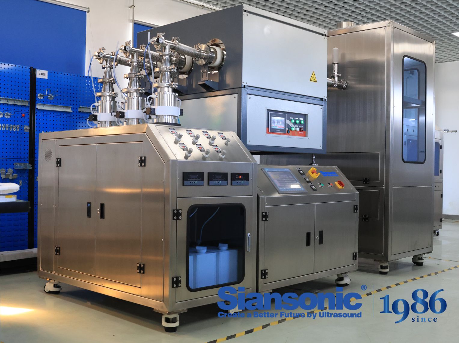
Standard off-the-shelf nozzles often force a compromise: you get either fine atomization or wide-area coverage, rarely both at the consistency required for advanced deposition work. Custom nozzle geometry changes that equation. By tuning orifice shape, internal flow channels, and exit edge profiles, it becomes possible to control droplet size distributions down to a few microns while maintaining a uniform spray pattern across the substrate. This level of precision matters when the goal is not just wetting a surface but building a functional layer with predictable thickness and morphology.
The real shift happens when those micron-scale droplets are used as building blocks for nanoscale films. A well-designed custom nozzle can produce overlapping droplet impacts that level and merge before drying, eliminating the pinholes and striping common with generic spray systems. Evaporation rate, impact velocity, and liquid rheology all interact at the nozzle exit, so a geometry tailored to a specific formulation turns an ordinary spray into a repeatable coating instrument. The result is a film that measures tens to hundreds of nanometers thick, with roughness controlled at the submicron level.
This approach also opens up options that fixed nozzle catalogs simply cannot address. Curved substrates, narrow trenches, or low-flow-rate applications benefit from nozzle shapes that place the spray exactly where it is needed without overspray or bounce-back. Rather than adapting the process to whatever nozzle is available, the nozzle becomes part of the process design itself, aligning droplet generation with the final film requirements from the first impact.
Precursor Chemistry and Solvent Selection: The Silent Performance Drivers
The choice of precursor rarely makes headlines, yet it sets the ceiling for what any downstream process can achieve. Metal salts with different counterions alter coordination geometry, hydrolysis rates, and the solubility window, which in turn shifts nucleation density and grain orientation. A nitrate might deliver sharp crystallinity but leave residues that demand aggressive annealing, while an acetate complex can slow the reaction enough to produce smoother interfaces—at the cost of lower throughput. These trade-offs are not captured in a simple purity specification; they live in the steric and electronic character of the ligand sphere.
Solvent selection operates in the same quiet register. Beyond dissolving the precursors, the solvent modulates intermediate species, hydrogen-bonding networks, and the evaporation trajectory during film formation. A high-boiling polar aprotic solvent may extend the processing window and improve wetting, but it can also trap residual solvent in the final layer or encourage unwanted oligomerization. Conversely, a low-boiling solvent speeds drying and reduces impurities, often at the expense of film uniformity. Matching solvent basicity and donor number to the precursor's Lewis acidity is where many otherwise well-designed chemistries quietly succeed or fail.
What makes these two variables especially potent is their coupling. A precursor that behaves ideally in one solvent can form stable intermediates or precipitate prematurely in another. Optimizing them independently often leads to local maxima; the real gains come from mapping the combined phase space—how solvation shells, counterion exchange, and drying fronts evolve together. Teams that treat precursor-solvent pairing as a design axis rather than an afterthought typically unlock morphology control and reproducibility that no post-treatment can fully recover.
Substrate Temperature Control That Keeps Films Crack-Free
The relationship between substrate temperature and film cracking is rarely a simple one. If the substrate runs too cool, arriving adatoms lack the mobility to settle into low-energy sites, building in tensile stress that eventually relieves itself through micro-cracks. Push the temperature too high, and thermal expansion mismatch between film and substrate becomes the dominant problem during cool-down, creating compressive stress or delamination. The practical solution is to hold the substrate within a narrow window where surface diffusion is sufficient to heal defects but the differential contraction after deposition remains tolerable.
Modern deposition systems approach this through staged thermal profiles rather than a single setpoint. A brief pre-deposition soak allows the substrate to reach thermal equilibrium so that early monolayers grow under consistent conditions. After nucleation, the temperature may be ramped downward very slowly while the film thickens, offsetting the accumulating intrinsic stress. Closed-loop control using a backside thermocouple or infrared pyrometer helps avoid sudden fluctuations, because even a short-lived hot spot can create a local stress concentrator that later becomes a crack initiation line.
In practice, the best crack-free results often come from pairing substrate temperature control with modest deposition rates and periodic pauses. These pauses give the growing film a chance to redistribute stress through surface and near-surface diffusion without requiring excessive temperatures that would damage temperature-sensitive substrates. Operators who learn to read the film's stress signature—visible through wafer curvature or in situ reflectivity—can fine-tune the thermal profile for each material system, producing dense, adherent films without the brittle failure modes that plague less careful processes.
From Single Wafer to Batch Processing: Scaling Custom USP Without Drift
Moving a finely tuned single-wafer recipe into a batch platform rarely works by simply loading more wafers. The local chemistry and thermal history each wafer sees changes when gas flows across a larger boat, when edge wafers sit closer to furnace walls, and when load size alters residence time. For a customized USP that has been dialed in on one wafer at a time, these shifts can show up as center-to-edge non-uniformity or lot-to-lot variation that did not exist in development.
The key to holding the process signature steady is to decouple what the wafer needs from what the tool naturally does. That often means re-characterizing the thermal profile with instrumented wafers, adjusting gas injection points or baffle positions so that each slot sees equivalent precursor exposure, and introducing deliberate soak steps that let the load reach thermal equilibrium before the critical process window begins. Small changes like wafer pitch, boat rotation speed, or exhaust tuning can be enough to bring batch results back in line with single-wafer baselines.
Batch scaling also benefits from statistical controls that treat slot position as a factor rather than noise. By monitoring mean thickness or key metrology values by zone, engineers can spot slow drifts before they exceed spec. Periodic requalification with a short single-wafer reference run creates a bridge between the original USP and the batch recipe, confirming that the process has moved in scale, not in character.
Reading the Telltale Signs of a Well-Engineered Thin Film
A well-engineered thin film rarely announces itself with a single dramatic flaw. Instead, it leaves a series of quiet clues across the substrate — subtle color shifts at the edges, a faint iridescence that moves as you tilt the sample, or an almost imperceptible uniformity in thickness that only reveals itself under oblique lighting. These are the signs inspectors learn to read first, before reaching for any instrument.
Look closely at the boundary where the film meets the uncoated zone. A crisp, clean line with no feathering or residue suggests the deposition parameters were held steady from start to finish. If you see a slight wedge in the interference fringes, that’s often a telltale of a gradient in chamber pressure or a drift in source temperature — not a fatal flaw, but a hint that the process was not fully locked in.
Run a fingernail gently across the surface. A well-engineered film will feel glassy and drag-free, with no micro-roughness or peel-back. Under a bright point source, check for pinholes by looking through the film at a dark background — a starfield of tiny bright spots means the nucleation stage was too hasty. None of these checks replaces metrology, but they’re the kind of hands-on reading that separates a routine coating from one that was truly dialed in.
FAQ
It generates fine, low-velocity droplets through a piezoelectric transducer, so precursor delivery stays gentle and evenly distributed. The narrow droplet size range and soft impact reduce overspray and pinholes, which helps when you need tight thickness control across a substrate.
You can adjust scan speed, nozzle height, and carrier gas flow independently for each chemistry. That means you can match droplet evaporation to the substrate's thermal profile, avoiding common edge-thickening or center-cooling effects seen with fixed setups.
Metal oxides like ZnO, TiO2, SnO2, ITO, and nickel oxide are common, but it also works with sulfides, doped perovskites, and some polymer composites, as long as the precursor can be dissolved or suspended in a sprayable solvent.
Substrate temperatures usually sit between 250°C and 500°C, depending on the precursor decomposition point. Higher temperatures promote better crystallinity and adhesion, but going too hot can cause premature drying of droplets before they reach the surface, leading to powdery films.
Yes, the custom build can be tuned for small samples down to a few square centimeters. You can use pulsed spray cycles and low flow rates to conserve precursor while still maintaining stable mist output and consistent film thickness run-to-run.
Droplet size is set mainly by the ultrasonic frequency and surface tension of the precursor. Higher frequencies give smaller droplets, while viscosity and solvent choice fine-tune the distribution. We typically operate between 48 kHz and 120 kHz depending on the target film roughness.
That distance controls how much solvent evaporates before droplets land. A shorter gap preserves more liquid on the surface, aiding dense, smooth films; a longer gap can produce rougher, more porous layers due to dried particle deposition. Fine-tuning it lets you shift from compact to nanostructured coatings.
Conclusion
Off-the-shelf ultrasonic spray pyrolysis equipment rarely delivers the film uniformity that precision thin film work demands. Standard systems drift in droplet size, precursor delivery, and thermal control, leading to pinholes, thickness gradients, and cracked coatings. The real difference comes from a custom nozzle built around the specific precursor and substrate, not a generic stainless steel tip. By tuning the nozzle geometry and excitation frequency, you can produce a narrow, repeatable cloud of micron-scale droplets that land wet enough to flow but dry quickly enough to avoid pooling. This micro-level balance turns a rough, polycrystalline deposit into a dense, nanoscale film with excellent step coverage.
Precursor chemistry and solvent choice are just as decisive, though often underrated. A solvent with the wrong evaporation rate leaves residue rings, while an incompatible precursor decomposes too early. Matching the chemistry with the nozzle's output and a substrate heater that holds temperature within a few degrees prevents thermal shock and keeps films crack-free. When scaling from a single wafer to batch processing, the custom system maintains its droplet size distribution and plume shape across every position, so the first and last samples show the same thickness and morphology. A well-engineered film reveals itself through uniform interference color, low haze, and stable resistivity or transmittance across the entire coated area; without those signs, the process is not yet truly controlled.
Contact Us
Contact Person: Ivy Zhang
Email: [email protected]
Tel/WhatsApp: +86 1081502288
Website: https://www.siansonic.com/